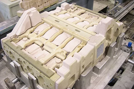
Review a sand casting mold as one chain: parting line, draft, shrink and machining allowance, core support, venting, gating, feeding and first-sample evidence. The goal is a design that can be quoted, tooled, inspected and repeated on one basis.

A drawing-to-trial guide for parting lines, draft, allowances, gating and checks that prevent repeat defects.
Sand Casting Mold Design: Draft, Allowance and Gating in Practice
-
Home>
-
Blog>
-
Technology>
Sand Casting Mold Design: Draft, Allowance and Gating in Practice
12
2026.11
A sand casting mold is not a negative copy of the drawing. It is a temporary tool that has to release the pattern, hold a core, survive pouring, feed contraction and let gas escape. Review it in that order. An approved drawing supplies the final requirement; the mold design translates that requirement into tooling decisions. Move one decision, and the others usually move with it.
A Sand Casting Mold Design Review Starts With Five Coupled Decisions
The first useful sand casting mold design review answers five questions in sequence: where the mold separates, how the pattern leaves, how much material is added for contraction and machining, how the core is held and vented, and how metal enters and feeds the cavity. A nominal pattern dimension only appears at the end.
What the Review Must Produce
This order matters because the decisions constrain one another. A parting line placed across a precision face can force extra flash removal and a second machining setup. A core needed to preserve a closed cavity adds print support, gas-escape planning and inspection access. A riser placed on a cosmetic surface can create a patch that costs more than moving the feed point earlier in the review.
Table 1. The five decisions that turn a casting drawing into a reviewable mold design.
Decision |
Required input |
Design output |
Failure if skipped |
|---|---|---|---|
Parting line |
Geometry, datums, machined faces |
Mold split and release direction |
Flash, mismatch and extra grinding |
Draft |
Release depth, texture, core direction |
Pattern and core release taper |
Scuffing, drag marks and mold damage |
Allowances |
Alloy, finish, distortion, datums |
Shrink and machining stock |
Undersize parts or wasted machining |
Core and vent |
Internal passages, gas volume, support |
Print, chaplet and vent layout |
Core shift, uneven wall, gas defects |
Gate and feeder |
Flow path, hot spots, alloy shrinkage |
Entry, filter, overflow and riser plan |
Misrun, turbulence and shrinkage voids |
The Pattern Is a Manufacturing Model, Not the Finished Part
A sand-casting pattern represents the casting before final machining. It may carry shrink compensation, machining stock, draft, core prints, fillets, parting features and distortion compensation. That is why copying the finished CAD solid into a pattern block is a weak starting point. Its tooling model needs to show how every functional surface will be produced and checked.
Drawing Control at RFQ
The approved drawing remains the technical authority. A sample can show what was produced, but it does not replace the drawing revision, material, process, inspection standard and marking agreement. During the RFQ, identify the drawing revision and the features that must not be altered by tooling compensation.
Send the drawing revision, 3D model if available, alloy and critical surfaces with the mold RFQ. Those inputs let the tooling review test the actual release and inspection plan, not a generic part shape.
Fix the Parting Line Before You Set Draft
Place the parting line where the two mold halves can separate cleanly, where cores are minimized, and where a small alignment error will not ruin a precision feature. Only after that boundary is fixed does the draft direction become meaningful.
A practical parting line should simplify mold construction, avoid unnecessary undercuts, keep flash away from critical surfaces, allow the casting to be removed and support measurement or machining. It should not cross a precision surface unless the drawing and process plan have accepted the extra finishing work.
-
Step 1: Mark the functional faces
Identify sealing, bearing, assembly and cosmetic faces before choosing the split.
-
Step 2: Test the release direction
Look for undercuts, deep pockets and surfaces that need a core or loose piece.
-
Step 3: Count the cores
Prefer the split that removes a core without moving controlled dimensions.
-
Step 4: Protect the datum scheme
Keep alignment-dependent features away from the split where the specification allows.
A Parting Line Is an Ownership Boundary
The line separates the cope, the upper mold, from the drag, the lower mold. It also assigns where flash can form, which half carries a core print, and how the two halves will align. A simple-looking zigzag split can create a more direct flow path but a harder tooling and cleanup plan. Compare both costs during that review.
When Mismatch Turns Into Cost
Mold mismatch occurs when the two halves do not align as designed. Visible consequences include a step, dimensional shift, extra grinding or a machining problem. A drawing that places a tight relationship across that boundary without a process reason is asking alignment error to become the only controlling variable.
Review rule: if a parting-line move removes one core but places flash across a sealing face, compare the added finishing, inspection and leak risk before accepting the change.
Use Undercuts Deliberately
Undercuts may require loose pieces, slides, collapsible cores or soluble cores. Some are valid because the alternative is a split that creates two precision setups. Record that decision in tooling approval, not at the first trial. That is also where pattern material and expected repeat demand enter the choice.
During drawing review, we treat the parting line as a decision that must be approved together with draft, core method and machining allowance. A late change after the pattern is cut can affect alignment, gate placement and the first-article report.
Set Draft So the Pattern and Core Can Leave
Draft is a release feature. It gives a pattern, core box or die enough taper to leave the mold without dragging sand or damaging an edge. General sand-casting practice often references about 1° to 3°, but the usable value depends on depth, texture, direction and whether the surface is internal.
The Cost of Too Little Release
Surfaces that are easy to draw in CAD may be difficult to strip from bonded sand. Deep pockets, manual molding, rough patterns and internal surfaces usually need more release margin. More draft can alter wall thickness or a mating feature, so it has to be reviewed against the drawing rather than added blindly.
Table 2. General draft references and the conditions that push the design toward more release angle.
Process or condition |
General reference |
What changes it |
Release check |
|---|---|---|---|
Sand casting |
About 1° to 3° |
Depth, texture and molding method |
Pattern pull and edge condition |
Internal surface |
Often higher than external |
Core support and removal direction |
Core drag and wall thickness |
Deep pocket |
Evaluate above base range |
Depth-to-width and tool access |
Scuffing, rounding, loose sand |
Textured or manual release |
Often beyond minimum |
Surface grip and operator variability |
Mold repair and visible drag |
When More Draft Saves More Than It Costs
A small increase in draft can reduce mold repair, operator dependence and first-trial tuning. It can also shift a wall, change a snap-fit gap or make a logo shallower. Ask which surfaces need release margin and which dimensions must remain controlled. Draft belongs on the tooling drawing with direction and datum, not only in a note saying “add draft.”
Check the Projected Shift
A useful planning test is a sectional check at the deepest point. Measure the projected shift caused by the proposed angle and compare it with the wall and machining limits. That simple check catches more problems than a visual pass over the CAD model because it connects release to the final dimensional budget.
The Draft Audit Has Three Answers
Positive draft: the surface removes cleanly in the approved direction.
Negative draft: an undercut requires a loose piece, slide, collapsible core or design change.
Marginal draft: possible in CAD, but risky for the selected sand, texture and operator method.
Include the release direction and the surfaces where draft cannot consume wall thickness. Those two facts let a foundry challenge the design without guessing which dimensions are disposable.
Split the Allowance Ledger Into Three Decisions
Separate shrinkage, machining stock and distortion compensation. They are related, but they are not one generic “allowance” added to every face. Shrinkage compensates for metal contraction. Machining allowance creates enough clean stock for the required surface. Distortion compensation responds to geometry and process movement.
Shrinkage Allowance Starts With Alloy, Then Gets Local
Metals contract during solidification and cooling, so the pattern must be larger than the final casting in the directions affected by contraction. The rough planning expression is: tooling dimension ≈ finished dimension × (1 + linear shrink). For a 400 mm feature with a 1.0% reference, the planning dimension would be about 404 mm before machining stock and local compensation are considered. That number is an example, not an approval value.
When One Shrink Factor Is Not Enough
Large or complex castings may not shrink uniformly. Ribs, cores, thick sections, mold restraint, uneven cooling, geometry and heat treatment can pull the part in different directions. Local dimensional compensation may be needed instead of one uniform factor. The tooling review should record the material basis and where the first sample will test it.
Table 3. Preliminary linear shrinkage references for pattern planning; final compensation requires project evidence.
Alloy |
General linear shrink |
Design note |
|---|---|---|
Gray iron |
About 0.8% to 1.1% |
Check section restraint and hot spots |
Ductile iron |
About 0.8% to 1.3% |
Confirm grade and feeding plan |
Carbon steel |
About 1.8% to 2.2% |
More shrink and feeding demand |
Stainless steel |
About 1.8% to 2.5% |
Confirm grade and heat treatment |
Aluminum alloy |
About 1.0% to 1.5% |
Check thin sections and distortion |
Brass / bronze |
About 1.0% to 2.0% |
Confirm alloy family and gate design |
Zinc alloy |
About 0.7% to 1.2% |
Do not use for sand-process claims |
Machining Allowance Is a Surface Decision
Machining allowance creates extra material on surfaces that will be cut. It has to absorb as-cast roughness, dimensional variation, mold shift, distortion, oxidation, cleaning and any heat-treatment movement. Large sand castings usually need more stock than small, tightly controlled castings, but every machined face should have a stated reason.
Stock Is Not a Safety Blanket
Too little stock can leave casting skin, a defect or inadequate cleanup after machining. Too much stock raises material use, machining time and tool wear, and may increase distortion. The drawing should distinguish as-cast, machined, datum-related and geometric dimensions so the review does not place stock on a feature that is already controlled by another requirement.
Shrink allowance: changes the tooling geometry for contraction.
Machining allowance: adds stock only where cutting will occur.
Distortion compensation: responds to a measured or predicted movement, not a generic rule.
Revision record: states which allowance moved and why.
Fact boundary: the ranges above are preliminary references. Actual compensation must follow material data, process knowledge, simulation where appropriate, sample production and dimensional verification.
-
Under-allowance test
Ask whether each machined face has enough clean stock after distortion and cleanup.
-
Over-allowance test
Ask whether the extra stock adds machining time, tool wear or distortion without a function.
Tooling release check: a pattern revision is not approved until the changed allowance has a marked surface, a drawing basis and a sample feature that will verify it.
Tooling Material Follows the Repeat Demand
A wood pattern can suit a prototype, large replacement part or low-quantity job because it is easier to modify and costs less at the start. Resin improves wear resistance, stability and detail for medium quantities. Aluminum, cast iron or steel patterns can support recurring production and better repeatability, but they cost more and are less forgiving of late design changes.
Tooling Choice and Change Cost
A split pattern aligns along the parting line. A match plate can carry both pattern halves plus runner and gate features, improving mold alignment and repeatability, but it also locks in more decisions. The buyer should send expected repeat demand and the cost of a later design change, not only the first-order quantity.
Tie the RFQ to the alloy, the machined faces and the expected repeat order. Those three inputs change both the allowance ledger and the pattern-material choice.
Support the Core and Give Gas a Route Out
A core creates the internal cavity, but the design is not finished when the core shape is drawn. The core needs a stable position, adequate strength, support through its prints, a route for gas, access for removal and a way to inspect the resulting passage.
Core rule: support, venting and removal are one review. A passage that cannot be held, cleaned or measured is not a finished internal feature.
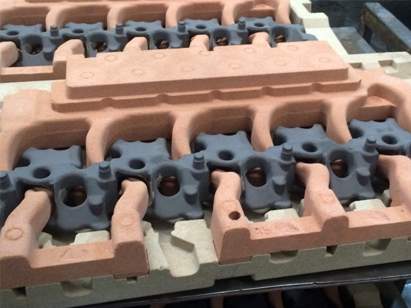
Core prints locate and support the core inside the mold. Insufficient support can allow core movement, uneven wall thickness, broken cores, blocked passages or dimensional rejection. A long or slender core may also need chaplets where the process permits, but chaplets affect fusion, leakage and corrosion risk and should not become an uncontrolled shortcut.
-
Core-support gate
Locate the core with prints, confirm the gas path, fix the coating, and put the core position in the first-article plan.
Core shift
Signal: uneven wall or blocked passage.
First check: print fit and metal pressure support.
Gas porosity
Signal: round pores with smooth walls.
First check: sand moisture, core dryness and vents.
Core breakage
Signal: internal debris or incomplete passage.
First check: handling, strength and support points.
Metal penetration
Signal: rough localized surface near the core.
First check: coating, sand condition and gap.
Venting Is Part of the Mold Geometry
Gas can come from moisture, binders, core material and the air displaced by metal. The design needs a path from the cavity high points and core areas to the outside. A vent cannot be added after the mold is closed if its position is already buried under a dense section or blocked by a core print.
Vent and Print Check
Vent placement and core support should be agreed together. Adding a vent can remove a support zone; moving a print can block a gas path. In the first trial, inspect the casting for rounded gas pores below cores or near the top of the cavity, then compare the result with the mold assembly record rather than changing pouring temperature alone.
Assembly test: if the vent, print and coating cannot be checked after closing, add a witness feature or inspection step before the design is released.
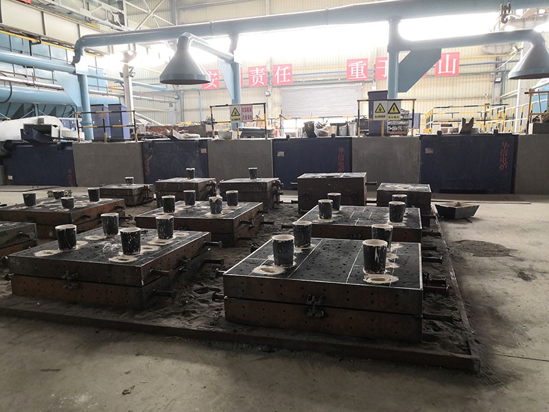
On our production floor, molds are checked for damage, contamination and assembly accuracy before pouring. That check is the last practical point to catch a displaced core or poorly sealed mold. The design should make those checks visible: print marks, vents and core position should be easy to confirm.
Design Gating and Feeding as One Flow System
The gating system controls how metal enters. The riser system controls how the casting is fed as it contracts. Treating them as separate drawings can produce a clean fill into a section that cannot stay sound. The flow path, hot spots and final solidification point must be read together.
Cope and drag: the split must align, seal and allow the pattern to be withdrawn without damaging the cavity.
Pattern release: draft and a practical parting line let the pattern leave without scuffing the sand.
Core support: prints locate the core, while vents and coatings control gas and metal penetration.
Gate flow: the runner and ingate fill the cavity without excessive turbulence or air aspiration.
Riser feed: the feeder supplies metal to the last solidifying section and supports directional solidification.
Venting: high points and core areas need a path for displaced air and binder gas to escape.
Figure 2. A simplified mold map for the six review zones. Without JavaScript, all six explanations remain visible.
Gating Controls Entry, Not Just Speed
A gating system may include a pouring basin, sprue, runner, ingate, filter, overflow and vent. The goal is to fill the cavity, reduce turbulence, limit air aspiration, trap slag and inclusions, control filling speed and support the intended solidification pattern. A larger gate is not automatically better if it adds erosion or makes the gate harder to remove.
Inputs That Change the Gate
The gating decision depends on alloy, casting size, wall thickness, mold material, pouring temperature, filling time, orientation, riser layout and defect sensitivity. Those inputs belong in the mold review. If the buyer only supplies a finished shape and a material name, the supplier is forced to infer which surface, section and hot spot matters most.
Risers Feed Contraction
A riser supplies molten metal as the casting contracts. Directional solidification aims to move the final liquid toward the riser, so the feeder remains liquid long enough to compensate a heavy section. Riser volume, location, section modulus, hot spots, orientation and feeding distance all affect the result.
Read the Defect Signal
A shrinkage cavity tends to form in a thick section and has a rough, irregular internal surface. Gas porosity appears rounded and often clusters where venting or core drying is weak. The surface signature is a clue, not a final diagnosis. The review should connect the location to the feeding path, mold assembly and pouring record before changing the tooling.
Gate Removal Is Part of the Layout
Every gate has to be cut, ground or machined away. Its location can change the visible surface, the machining setup and the yield. Put the gate where removal is practical and where the remaining mark will not violate a sealing or appearance requirement. The same rule applies to a riser pad: a feeding aid can become a finishing problem if its location is ignored.
Mark the cosmetic and sealing faces before approving gate and riser locations. A two-line change on the RFQ can prevent a costly finishing route later.
Prove the Design With a First-Article Trial
The first tool trial is a measurement event. It checks whether the mold can fill, release, hold the core, feed shrinkage and produce the dimensions and surface agreed in the drawing. It is not automatic production approval, and the first trial does not need to be perfect.

First-article review board
0 of 8 checked
What the Trial Must Expose
The trial should show how the mold fills and where the casting is difficult to release. It should expose the location of flash, hot spots, core movement and machining stock. It should also give the inspector a clear basis for deciding which feature needs a tooling correction and which feature is already stable.
Close the Correction Loop
A correction can include a dimensional adjustment, gate or runner change, revised vent, riser modification, draft correction, core-position adjustment, local compensation or surface polishing. The record should link the change to the trial result. Without that link, a second sample proves that something changed but not whether it addressed the intended failure.
Approval Is More Than “The Sample Looks Good”
Final sample approval should confirm the drawing revision, material, casting process, dimensions, machining, surface treatment, inspection standard, packaging and markings. The approved drawing remains the primary technical authority; the sample is a production reference, not a replacement for the specification. Any later tooling modification should record the reason, affected dimension and approval.
Read Inspection Evidence Against the Design Intent
A dimension can pass while the mold design remains weak. Use the inspection record to connect each critical feature back to the reason it was designed that way: release, core support, machining, sealing, assembly or appearance. This is how first-article evidence becomes useful for repeat production.
Does every sand-casting mold need a core?
No. A simple open cavity may need no core. Cores are used to form internal passages, holes or recessed features. The design review should still ask whether changing the parting line or opening a cavity removes the core without adding a worse finishing problem.
Can one shrinkage percentage be used for the whole part?
It is a starting reference, not a sufficient assumption for a large or uneven casting. Ribs, cores, thick sections, mold restraint, heat treatment and cooling differences can create local movement. The tooling plan should identify where the sample will verify the compensation.
Which test proves a casting has no internal shrinkage?
No single visual check proves it. Depending on the risk and purchase requirement, RT, UT, pressure testing, sectioning or CT may be used. The acceptance method should be written before production, with the location and acceptance basis defined.
When is a first trial considered complete?
The trial is complete for the agreed stage when the drawing revision, process, dimensions, surface, core position, gating and machining intent have a documented result. A tool correction may still be required. The approval record should state what remains open.
What if the drawing has no datum or inspection method?
The supplier cannot build a reliable first-article plan from an undefined measurement basis. Clarify the critical features, datum structure and acceptance record before tooling approval. If the drawing is incomplete, contact us for details on the missing input rather than accepting an assumed datum.
Do Not Substitute a Visual Check for the Drawing
A visual check can catch flash, sand adhesion, cracks and obvious surface defects. It cannot replace dimensional measurement or the inspection method needed for an internal risk. The record should state the method, the stage and the result. Material certificates and process records support traceability, but they do not prove that the parting line, gating or feeding met the design requirement.
Send the Inputs That Change the Mold Review
A sand-casting mold quotation is more useful when the buyer sends the few inputs that change the tooling route. A 2D drawing or physical sample is needed to evaluate a custom casting project accurately. A 3D model helps, but it does not replace the drawing revision, tolerances and acceptance requirements.
The RFQ package that changes the answer
01 Approved 2D drawing and revision
02 3D model if available
03 Alloy, grade and heat treatment
04 Batch and expected repeat demand
05 Machined and as-cast surfaces
06 Datum scheme and critical dimensions
07 Inspection, marking and packaging requirements
08 Any pressure, NDT or special acceptance method
What We Need to See First
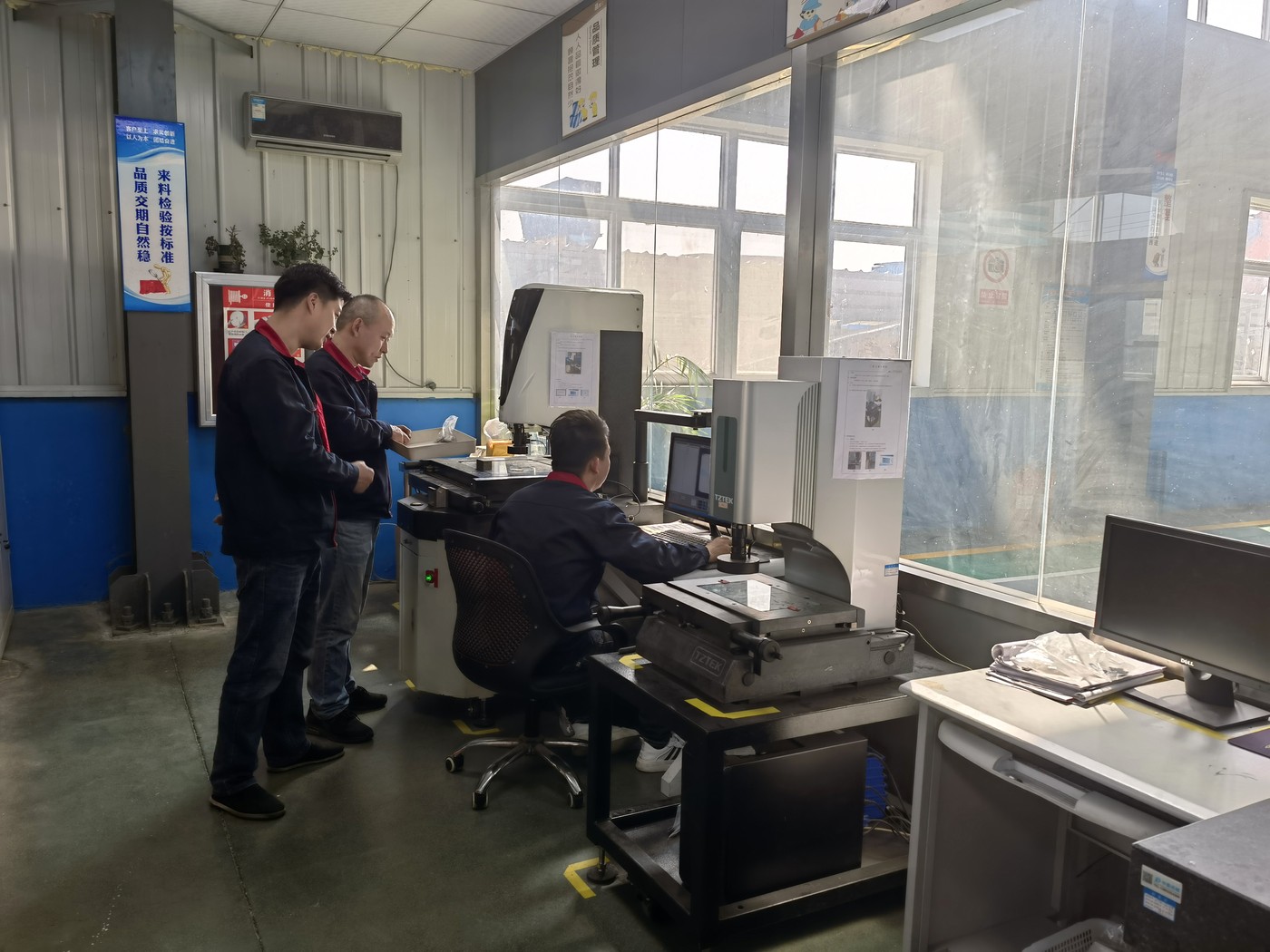
On our drawing reviews, the first pass looks for the release direction, the core method, the surfaces that will be machined and the dimensions that must not move. We then compare the pattern-material choice with the repeat demand and define the first trial. The result is a mold review that can be quoted and inspected on the same basis.
Missing Facts Stay Missing
If a fact is missing, state it clearly instead of filling the gap with a generic assumption. Where HULK Metal needs a specific capacity, tolerance, certificate, lead time or test result to answer, contact us for details. The answer should come from the project record, not from a competitor’s sales claim.
Useful review question: which drawing input, if changed, would change the parting line, draft, allowance, core method or gate location? Start there.
HULK Metal’s OEM workflow can coordinate drawing review, qualified casting partners, machining, inspection, packaging and delivery, but the drawing and approved specification remain the authority. Send the drawing, alloy, critical surfaces and expected batch so the mold design can be reviewed as a production system.
Revisit a decision
Article Navigation
Others You Might Want to Know
Article Navigation
Industries
Foundries
Athers Articles About Metal Casting
-

October.24, 2026
Casting Defects: A Photo-Led Guide to Misruns, Cold Shuts and Sand Defects
READ MORE
-
October.23, 2026
Machining Allowance for Castings: How Much to Leave
READ MORE
-
October.15, 2026
Casting Tolerances by Process: ISO 8062 Grades vs What Foundries Actually Hold
READ MORE
-
May.23, 2025
Casting Molds: The Heart of Precision Casting
READ MORE
-
March.26, 2025
Sand Casting vs. Die Casting: Which is Right for Your Project?
READ MORE